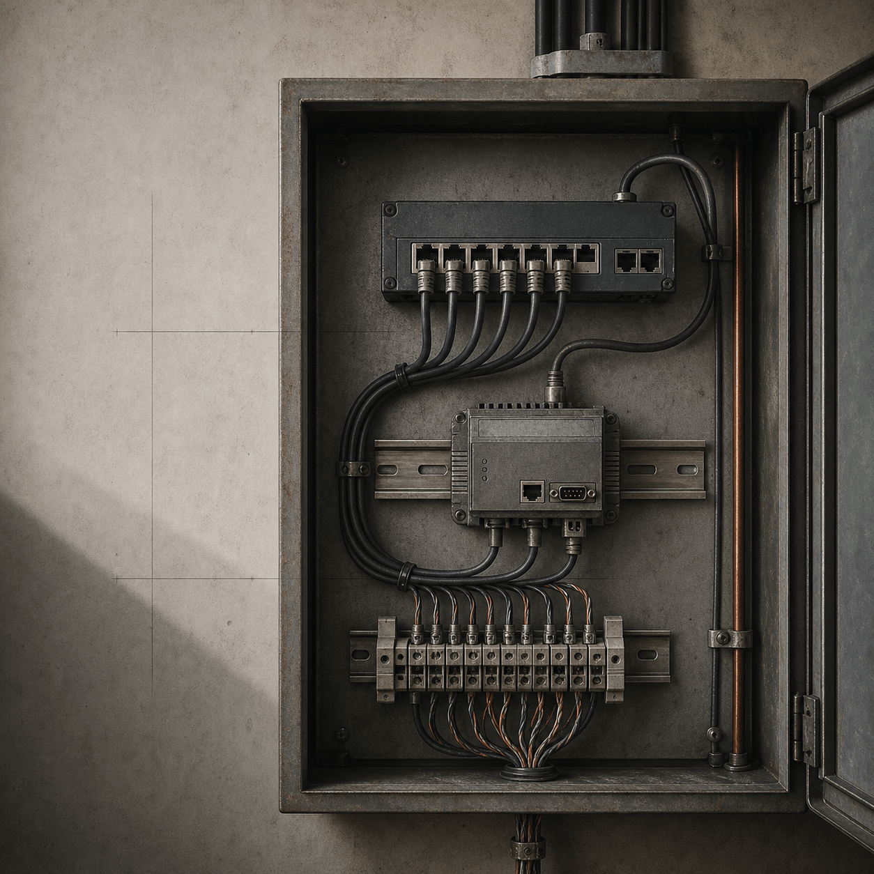
· Industrial Protocols · 10 min read
Modbus RTU Survival Guide: RS485, Noise & Troubleshooting
Is your Modbus network failing at night? A deep technical guide on termination, fail-safe biasing, grounding, and using an oscilloscope to see noise.
Modbus RTU Survival Guide: diagnose the RS-485 bus before blaming Modbus
An RTU request can be perfectly formed and still fail before the receiver recognizes a byte. This guide owns that physical-layer boundary: differential signaling, topology, termination, idle bias, reference strategy, measurements, and staged fault isolation. It does not explain MBAP, transaction handling, or gateway protocol architecture; use Modbus RTU & TCP for that. It also does not catalog function codes or authorize writes; use Modbus Function Codes for request semantics and controlled-change rules.
Safety before testing
RS-485 work can expose people and equipment to panel voltages, ground-potential differences, transient energy, and an unintended OT control path. Qualified personnel must follow the site method statement, equipment documentation, de-energization and LOTO procedure, PPE requirements, and isolation rules. Never attach an unknown USB adapter, move a terminator, connect a scope ground, scan unit IDs, change serial settings, or send a write on a production segment merely to investigate a timeout.
The byte calculation below uses only the Python standard library. It does not access a serial port, transceiver, powered cable, oscilloscope, converter, controller, or industrial process. This guide includes no measurements from a specific installation. Any authorized measurement must record instrument, probe method, location, conditions, and result. A correct calculation is not evidence of hardware success.
Differential signaling is not immunity
An RS-485 receiver decides from the voltage difference between its two signal conductors, not from either conductor relative to an arbitrary local ground. A twisted pair therefore helps reject noise that couples similarly into both wires. It does not make the installation immune to interference, erase cable loss, establish a safe reference, or make device labels interchangeable. “A” and “B” markings are not universally consistent across products; verify polarity from each device drawing and prove it only with an approved test.
The receiver and transceiver also have finite differential thresholds, common-mode range, input loading, data-rate capability, and transient tolerance. TI’s design guide summarizes the baseline TIA/EIA-485 common-mode range as -7 V to +12 V, but a selected part may differ and a surge rating is not a continuous operating allowance. A bus can have a plausible differential waveform while one node is outside its allowed common-mode range. Treat the datasheet for the installed transceiver, its supply, isolation rating, and protection network as the governing limit.
Draw the bus before changing it
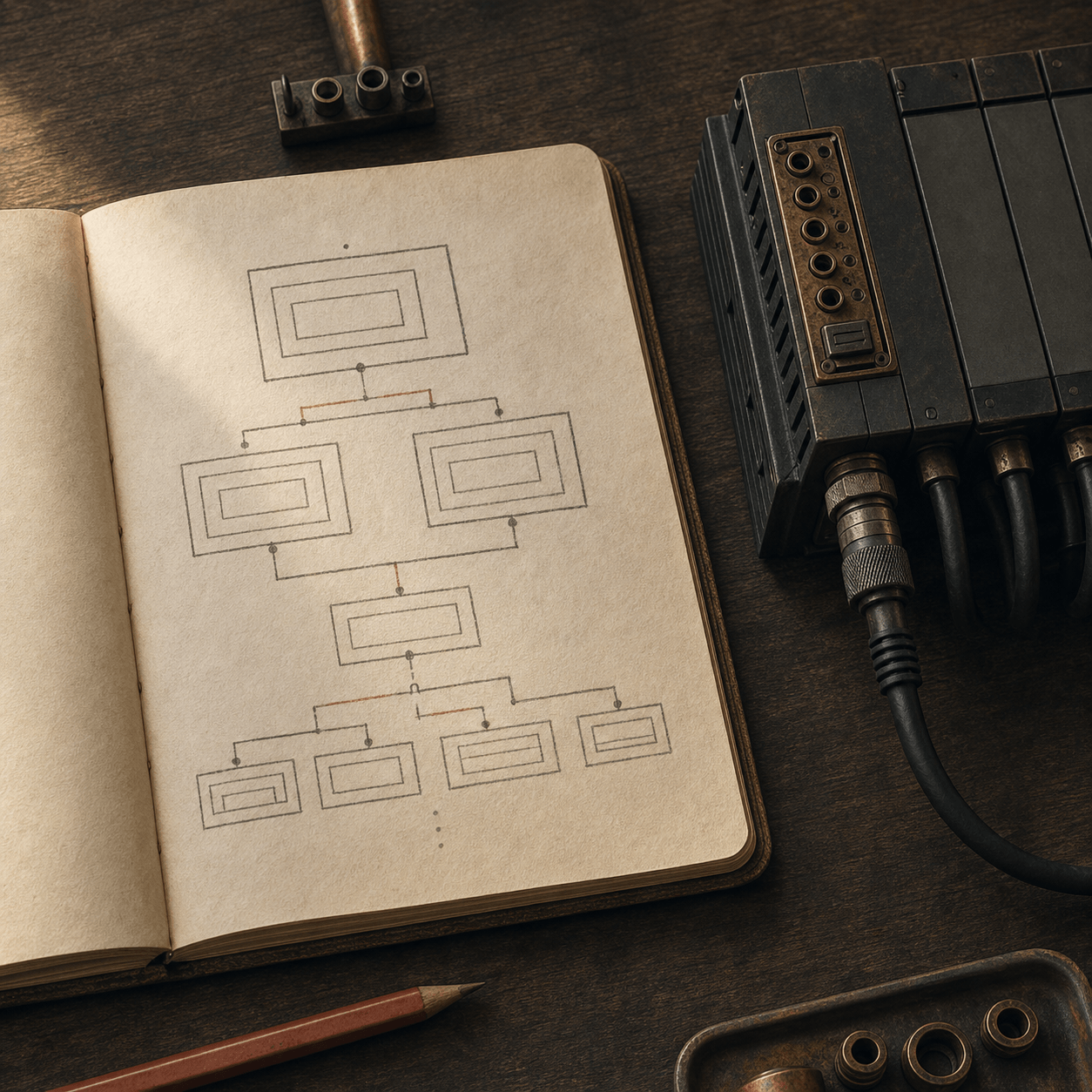
The intended multidrop shape is one trunk with short stubs. A star or long drop creates branches with different delays and reflections. First sketch each node, trunk and stub length, cable, bitrate, device switch, shield, terminator, and power-panel boundary.
Start with the actual installation rather than the commissioning drawing. A junction box may hide a third branch, a spare cable may still be connected, or a replacement device may have its termination switch enabled. Disconnecting or moving conductors is electrical work, not a desk exercise. On an authorized isolated bench, change one approved variable at a time and retain the former state so the result is reversible.
Termination controls reflections, not all faults
A termination resistor belongs at each physical end of the trunk because it is intended to match the cable’s characteristic impedance and absorb a traveling edge. TI commonly illustrates 120-ohm termination, but 120 ohms is a design starting point, not a universal repair value. Cable construction, topology, bit rate, node loading, and the equipment design determine whether the installed network needs and supports that value. Do not add a resistor at every device: parallel terminators lower the effective bus resistance and can reduce the differential signal margin.
An unterminated end can reflect a fast edge. On a scope, that may appear as a delayed step, ringing, or a second threshold crossing after the main transition. Its time relationship to the original edge is evidence to compare with cable length and propagation delay, not proof that “termination is wrong.” Excessive stubs, a probe artifact, a bad connector, or a driver at its limit can resemble the same picture. This guide does not report a waveform or installed termination value.
Failsafe biasing defines an idle bus
Half-duplex nodes release the pair between transmissions. Without a defined idle differential state, noise or leakage can let a receiver interpret transitions where no driver is active. Some modern transceivers include receiver failsafe behavior for open, shorted, or idle inputs; other designs use an external bias network. Whether bias is internal or external is a property of the installed parts and circuit, not something inferred from a successful Modbus read.
External bias must be designed with termination, supply tolerance, receiver threshold and hysteresis, the number and unit-load class of receivers, and worst-case current. Copying pull-up and pull-down values from another product can make idle margin worse or overload a driver. Record the schematic revision and manufacturer guidance, then calculate or bench-review the loaded idle state under the approved design. This guide does not report an idle-voltage measurement or bias-network acceptance.
Cable, shield, ground, and isolation are separate decisions
Use a cable and installation method specified for the environment and the selected interface. Twisted-pair conductors carry the balanced signal. A shield is an electromagnetic-interference control; a signal reference is a circuit decision; protective earth is a personnel-safety system; and an isolation barrier limits energy transfer across domains. They can be connected in a documented design, but they are not interchangeable conductors.
Do not turn a shield drain into a protective-earth conductor or add a reference jumper because it “fixed noise” once. Ground-potential differences between panels, buildings, or machine sections can exceed a non-isolated transceiver’s allowable common-mode range or create hazardous fault current. Where the approved design requires galvanic isolation, use devices and wiring practices rated for the installation, including their power-isolation and surge requirements. Follow local code, manufacturer instructions, and the responsible electrical engineer’s design for shield bonding and reference treatment.
What to capture before touching the wiring
Separate symptoms into timeouts, CRC failures, valid exception responses, and implausible but structurally valid values. CRC failures and malformed frames justify a physical-layer hypothesis; a valid 83 02 response, for example, is a protocol-level illegal-address result and belongs in the function-code investigation. Capture the time, initiating system, unit, serial settings, raw request and response, error counter, firmware revision, operating state, and nearby events such as motor starts or welding. Correlation suggests a testable coupling path; it is not evidence that the nearest machine caused the fault.
Preserve a known-good frame and compare it with the failing transaction at the same serial settings. Avoid broad retries: they can conceal timing evidence, load a damaged bus, and are unsafe around writes. A passive capture at an authorized boundary is preferable to inserting a new active converter. If intervention is necessary, use an isolated, approved lab segment and a read-only request whose expected result and rollback boundary are documented.
Oscilloscope workflow and interpretation
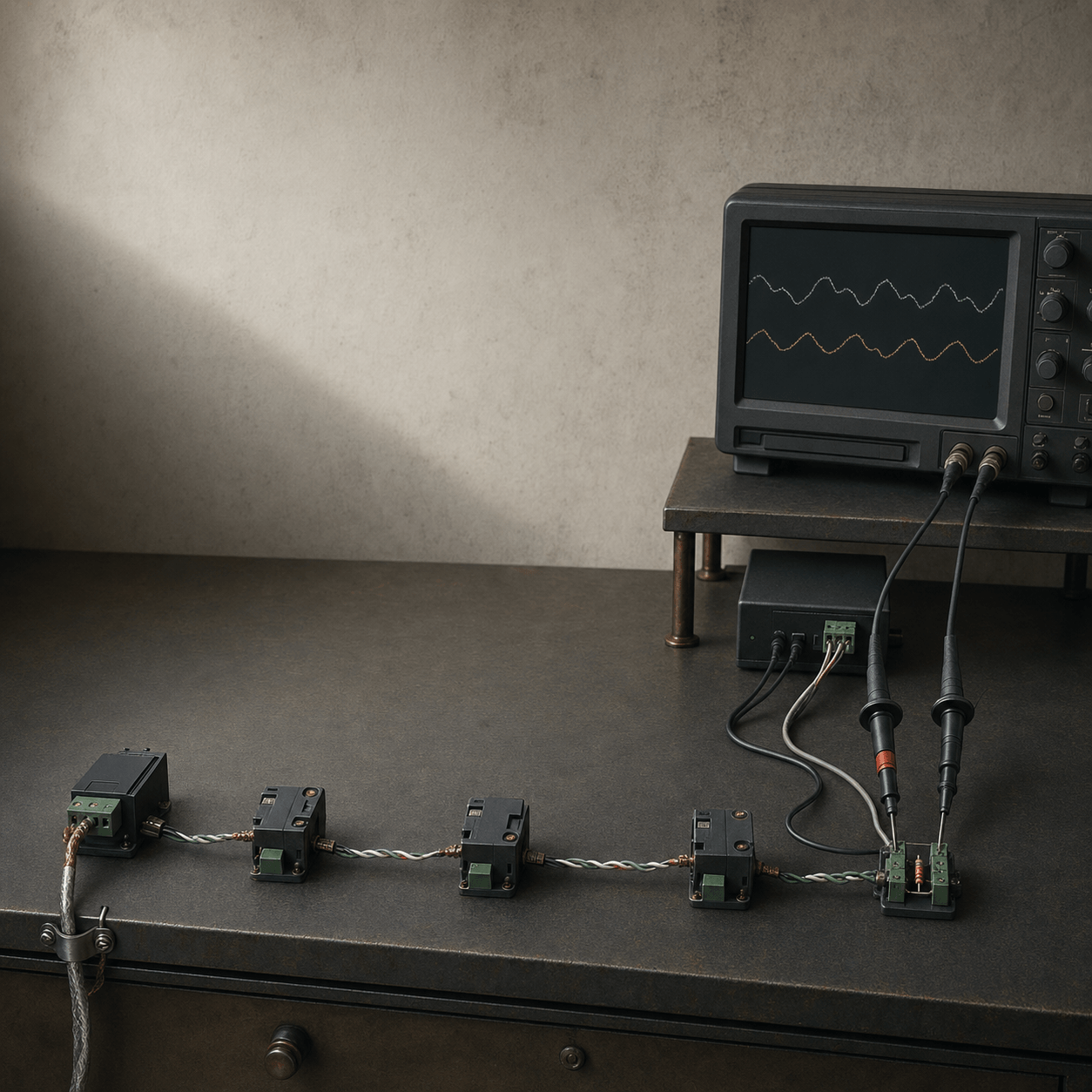
Before interpreting a waveform, record scope bandwidth, probe model and attenuation, whether the view is true differential or reconstructed from two channels, probe reference method, capture point, trigger, bus configuration, and request timestamp. An unsuitable ground lead or reference can add ringing that is not present on the bus. Connecting an earth-referenced bench scope to the wrong point can also create a fault path. Use a properly rated differential probe or the approved isolated measurement method; do not improvise around a panel’s earthing scheme.
Compare the same read-only request at a known-good location and a failing location. Inspect differential idle state, transition shape, amplitude at the receiver, delayed features after an edge, and the relation of each conductor to the permitted common-mode range. A reflection normally has a delay relative to the edge that launched it; noise often correlates with an external event; idle ambiguity appears when no driver is active. Those are hypotheses to test against topology and timing, not diagnoses by screenshot. This guide does not include a scope trace, amplitude, common-mode measurement, or identified noise source.
CRC example
The example calculates the Modbus CRC for the request payload 11 03 00 64 00 02. The expected numeric CRC is 0x4487; Modbus RTU transmits its low byte first, so the complete frame ends 87 44. The command intentionally changes the requested quantity and asserts that the original CRC no longer matches. It proves repeatable local arithmetic and a bad-frame vector, not receiver sensitivity, shielding, timing, termination, or a device response.
python3 - <<'PY'
def crc16(data):
    value = 0xFFFF
    for byte in data:
        value ^= byte
        for _ in range(8):
            value = (value >> 1) ^ 0xA001 if value & 1 else value >> 1
    return value

payload = bytes.fromhex('110300640002')
assert crc16(payload) == 0x4487
assert crc16(bytes.fromhex('110300640003')) != 0x4487
print('OK: CRC example passed')
PY
This example checks CRC arithmetic and a changed payload only. It does not cover electrical behavior, a serial port, or a control system.
Staged troubleshooting sequence
- Freeze and classify. Stop unapproved changes, identify whether the symptom is timeout, CRC error, exception, or semantic value problem, and retain raw evidence.
- Verify configuration. Check documented baud rate, parity, data bits, stop bits, unit identity, A/B labels, firmware, and approved gateway configuration. Do not “try settings” on a live bus.
- Inspect topology. Reconcile the physical trunk, ends, stubs, terminators, cable, shield continuity, and node count with the approved drawing.
- Measure safely. At authorized points, compare the same read-only transaction with an appropriate differential method. Record the method and conditions before changing a hypothesis.
- Isolate on a bench. Use approved isolated equipment and a known-good segment to narrow cable, node, or transceiver behavior without expanding production risk.
- Escalate deliberately. Return to site only under an approved procedure with a rollback plan, owner authorization, and acceptance criteria. A restored reply alone is not acceptance evidence.
Deployment checklist and limits
Use this checklist as an acceptance-record outline, not as permission to energize or alter equipment. It makes the missing evidence visible: an apparently stable reply is not enough when the drawing, installed switch positions, transceiver ratings, or measurement method are unknown. Record who authorized the work, what changed, the exact read-only transaction, and the restoration state before handing a link back to operations. The site acceptance procedure remains the authority for any energized measurement or production return.
- The as-built bus diagram names trunk ends, stubs, cable type, terminators, node count, and serial settings.
- The transceiver datasheet and circuit revision are checked for common-mode, loading, failsafe, isolation, and transient limits.
- Shield, signal reference, protective earth, and isolation decisions are documented by the responsible design authority.
- A passive capture and any authorized electrical measurement have instrument, point, conditions, and result recorded separately.
- The commissioning request is read-only, has an expected value, and does not depend on a production write or scan.
- Rollback restores only the approved configuration and preserves the original capture for review.
This guide cannot certify EMC performance, cable suitability, personnel safety, regulatory compliance, device interoperability, or process availability. It deliberately avoids a universal maximum length, data rate, resistor value, shield bond, or transceiver selection because those claims require the actual cable, environment, and approved design. For RTU framing and TCP gateway boundaries, continue with Modbus RTU & TCP; for address, response, exception, and write semantics, continue with Modbus Function Codes.
References
- Texas Instruments, The RS-485 Design Guide, SLLA272D, revised May 2021. https://www.ti.com/lit/pdf/slla272
- Texas Instruments, RS-485 Basics Series, SLLA545, February 2021. https://www.ti.com/lit/pdf/slla545
- Texas Instruments, AN-1057: Ten Ways to Bulletproof RS-485 Interfaces, SNLA049B, revised April 2013. https://www.ti.com/lit/pdf/snla049
- Modbus Organization, Modbus over Serial Line Specification and Implementation Guide V1.02. https://www.modbus.org/file/secure/modbusoverserial.pdf